Testing cables at high voltages can help determine the presence of moisture, flux, or contaminants that may have penetrated the insulation or connector backshell breaks, and ensures that the insulation between wires can withstand temporary voltages higher than the normal working voltage offset without decomposing. The results of the high-voltage test usually show the insulation resistance between the wires in the hundreds of megohms or higher. It is not uncommon for test specifications to call for 5 gigaohms of insulation resistance.
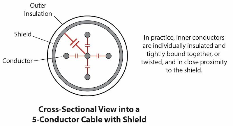
Many high reliability cables include a braided shield surrounding all conductors. The shield prevents external electrical interference from coupling to the signal on the inner conductor and prevents electrical noise that may be generated by normal signals on the inner conductor from radiating into the environment. However, shielded cables complicate high-voltage testing because the capacitance of the shield relative to the inner conductor is greatly increased. Since the shield has a much larger surface area compared to the wire, the capacitance between the shield and the conductor increases proportionally. Capacitance increases further with cable length.
As the capacitance increases, so does the energy stored in the live shield to levels that can be hazardous to operators and, in the event of insulation breakdown, can damage the insulation of the cable due to arc heating. Note that the energy stored in a capacitor increases directly with the capacitance and the square of the voltage: E = ½ CV 2 .
Many test specifications require the shield to participate in the high voltage test as an additional conductor. The following statement is taken from a typical specification: When a test potential of 500 Vdc is applied between the shield and the conductor, the assembly shall exhibit an insulation resistance of not less than 500 MΩ.
Automatic high voltage testing equipment will apply a DC voltage to one conductor while keeping all other conductors at zero volts. Typically, for each wire, the voltage is ramped up, held for a "dwell time", and then ramped down after the test on that wire is complete. Repeat this process for each conductor in the cable, for example, a five-conductor cable, and the up-pause-down cycle will repeat five times, each time on consecutive wires. With this process, the insulation of a wire is actually tested twice, once when the wire itself receives a high voltage (+ to - polarity of the wire insulation) and once when the same wire is held at zero volts while The other wire is tested later when it receives voltage (- to + polarity on the first wire).
When we include the shield in the test, it's just another "wire" in the cable and follows the same process. In this case, when a voltage is applied to the shield when all other wires are at zero volts, the shield will hold more charge than when a voltage is applied to any one of the wires where the shield is at zero volts. As the charge on the shield increases, much more energy is stored in the shield than in the wire, and an inadvertent discharge through insulation breakdown or human contact will cause considerable current to flow. This, in turn, could melt the pinhole in the insulation, rendering the cable damaged and unusable, or worse, creating a dangerous shock hazard for the operator if the discharge was caused by human contact. Even the act of charging the shield on the upramp can exceed the tester's trip current (the preset current limit indicating breakdown) before the test voltage is reached.
Typical polymer plastics used in wire insulation prevent current from flowing in any direction as well as the electric field vector. We will then see that between any two wires, the insulation acts with the same leakage resistance whether we apply a high voltage to wire A while keeping wire B at zero volts, or vice versa. Since shields are considered conductors and are typically tested in both directions, we can avoid pinhole insulation damage and increased risk of electric shock by not applying high voltage to the shield, while still providing power to each wire with the shield The applied high voltage was maintained at zero volts during the test. Doing so in no way reduces the validity of the test.
Referring to the test specification given earlier, apply the 500 Vdc test insulation between the conductor and the shield as if it were applied between the shield and the conductor. Therefore, by testing only between the conductor and the shield, we eliminate the risks associated with applying voltage to the shield.
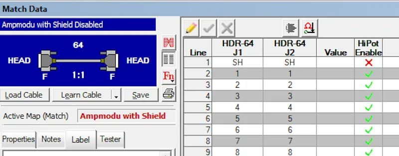
In the CableEye ® tester manufactured by CAMI Research, any conductor can suppress high voltage during testing by simply indicating it in the "HiPot Enable" column. In this screenshot we show how to suppress high voltage applied to the shield:
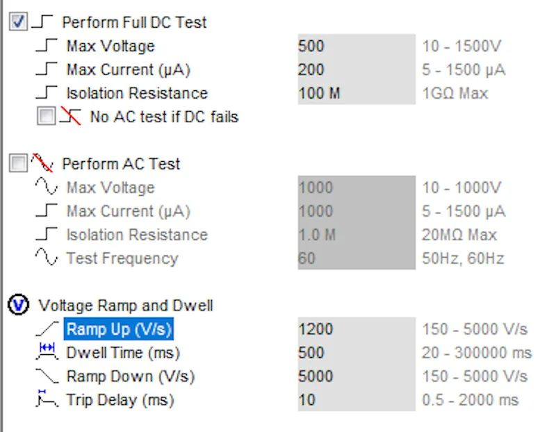
Even if we don't apply a voltage to the shield, shielded cables can still have problems when hi-pot testing, because as the length of the cable increases, the conductor itself stores more and more charge. Typically, in this case, the charge current during ramp-up can approach or exceed the normal trip current. This is compensated for by reducing the ramp rate so that the instantaneous charge current never reaches the trip current. This shows how it's done using the CableEye tester. In this screenshot we reduce the boost from 5000 V/s to 1200 V/s:
Some cables have multiple sets of shielded wires combined into a bundle, such as shielded twisted pairs, or bundles of coaxial conductors braided into a single cable. Capacitance problems become even worse when the inner shields are combined and high voltages are applied. Additionally, the reported leakage is the sum of all leakage between parallel shielded busbars and the wires they shield. This sum will likely exceed the allowable leakage and cause the calculated insulation resistance to be too low, causing the test to fail, especially if there are a large number of shields grouped together. The average leakage is of course the sum of the leakage in the group divided by the number of conductors in the group. The more wires the shield contains, the greater the leakage (normally) and the lower the overall insulation resistance of the group.
For the above reasons, as long as the shield remains at zero volts while testing other wires at high voltage, it is not necessary to apply voltage to the shield conductors to accurately test insulation resistance. When high voltages are suppressed across all shields, the cable will not fail due to unwanted stacking of leakage currents.
Aichie provides high -quality busbar low -voltage auto wiring harness and high -voltage ev cable assembly around the world. It has introduced new production equipment, which greatly improves the quality and efficiency of production. Customers are widely distributed in Europe and North America. Production employees and experienced engineering teams and sales teams serve our customers; please contact us now! We will provide you with competitive prices!
AICHIE Tech Electronics Co.,Ltd
Email: sales03@aichie.com
Mobile/Whatsapp/WeChat: (86)18027502150
Skype: live:.cid.8643b3df38ff8b5
Tags :
Runtian Industrial Park, No. 3 Futian Road, HetianXia, Shijie Town, Dongguan City, Guangdong Province China
Rm 3104 Huarong BLDG No.178 Mingtian Rd Futian Central Shenzhen City China
1859, tò ban do so 10, khu pho 1, Phwòng Vinh Tân, Thành pho Tân Uyên, Tinh Bình Dwong, Viet Nam
© 2026 Aichie Tech Electronics Co Ltd.All Rights Reserved.
XML Privacy Policy